F.L.O.D. or First Line of Defense is an electronic door lock with Haptic Feedback I made for my workshop at home. Convinced that someone was sneaking into my lab and stealing my precious tools and components, I decided to do something. Standard key-lock could be used but I did not want to limit myself when I would spontaneously have an idea and want to prototype it but would not be able to because I misplaced my key.
Commercial products which have similar functionality do exist but they were too expensive and over-kill for my application. Hence I made this simple one using parts I had laying around: an old latch lock, a servo, matrix keypad and an arduino nano.
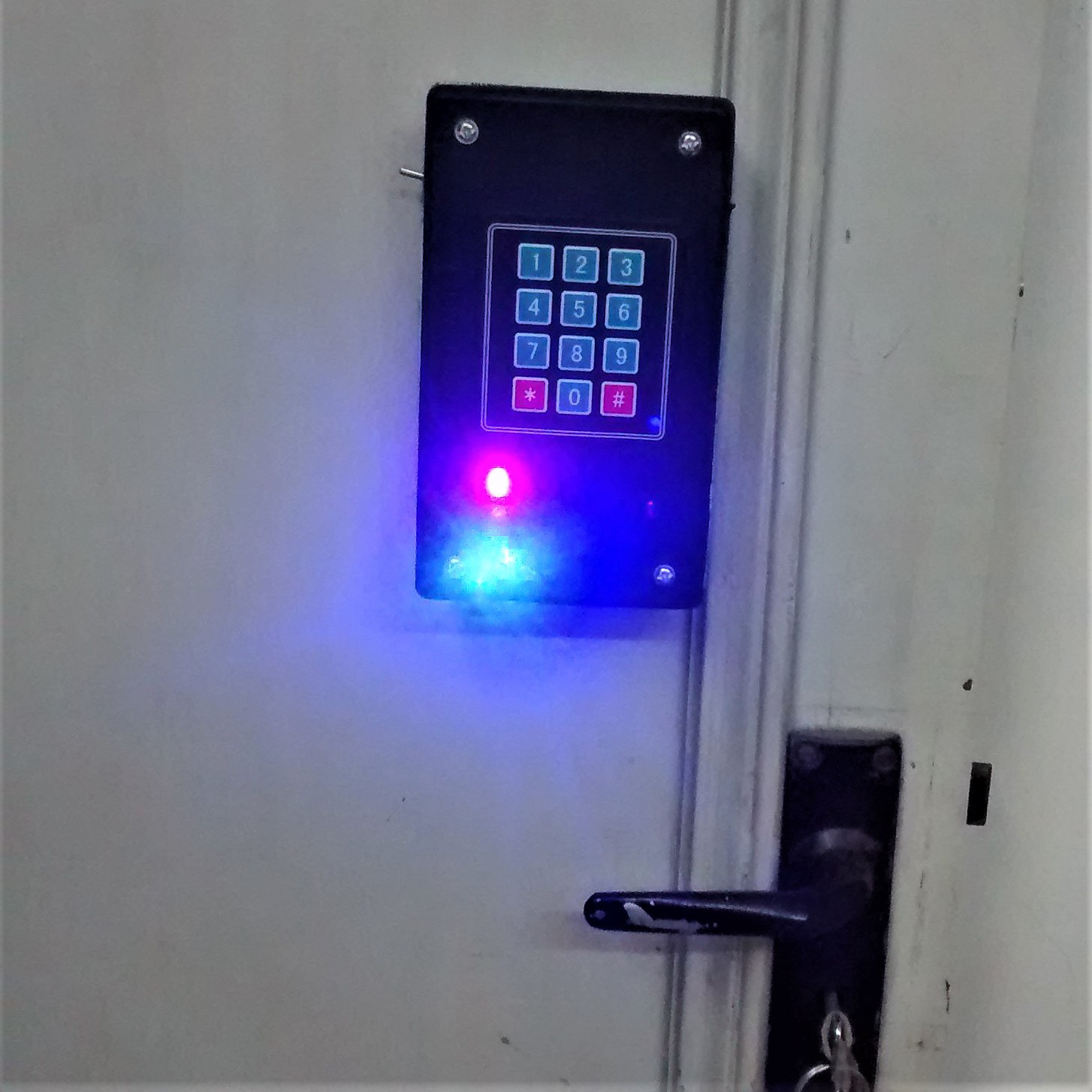
One unique thing about my design is that it has Haptic Feedback. The keypad I used was capacitive rather than tactile, which made it difficult for a user to know if the keys had been pressed or not. I used a motor with an unbalanced weight attached to its shaft inside the housing of the lock, which would 'pulse' whenever a key was pressed. This made it very easy to know if a key had been pressed and increased the ergonomics greatly.
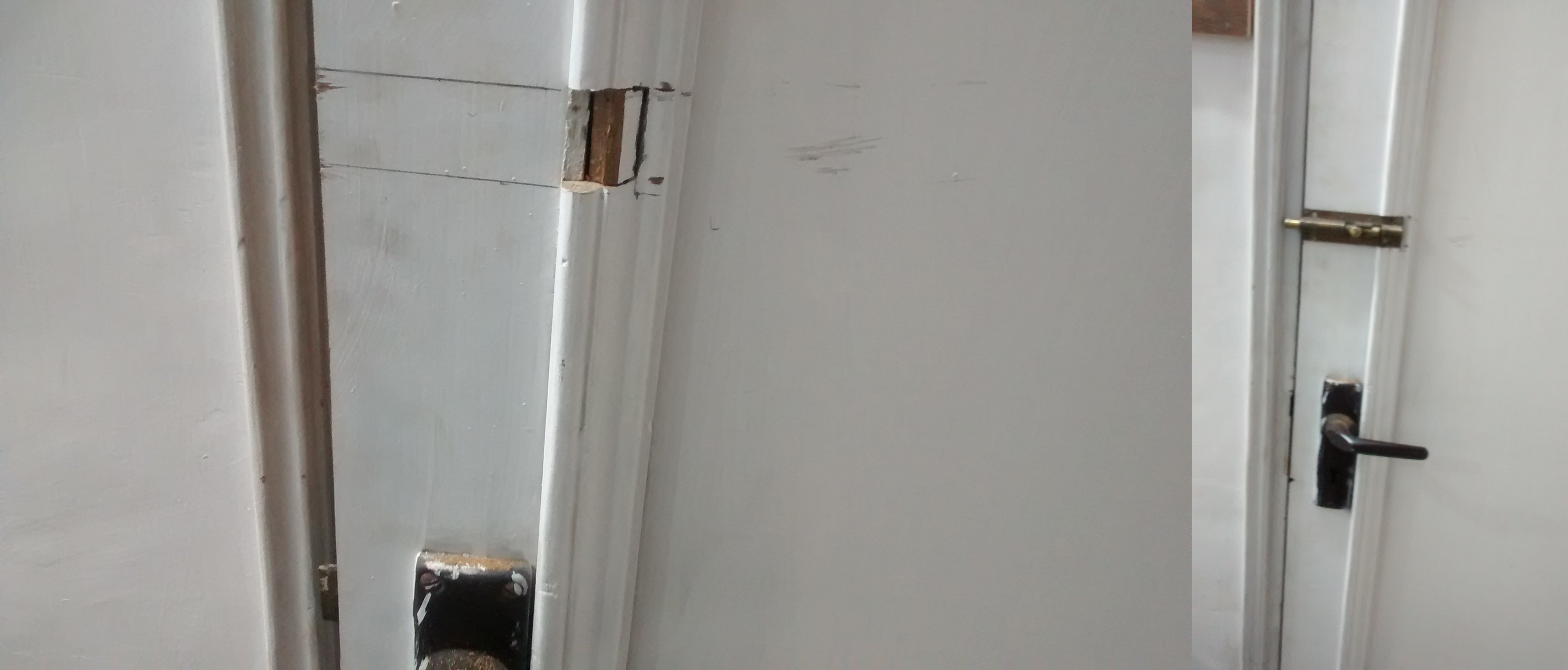
Attaching the mechanical latch lock on the inside. This would take all the weight when the door was forced to be open, keeping the servo from breaking.
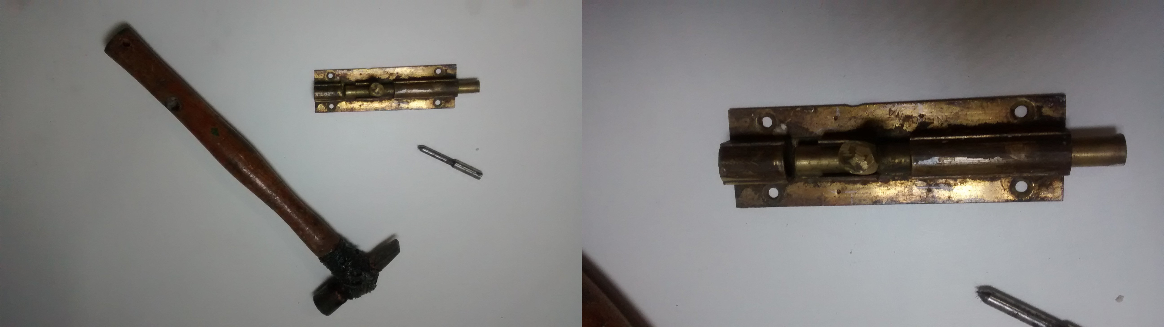
Once the lock was attached to the door and made sure it was locking, I modified the knob to pass a steel wire through. This would act as a mechanical connection between the servo and the lock.
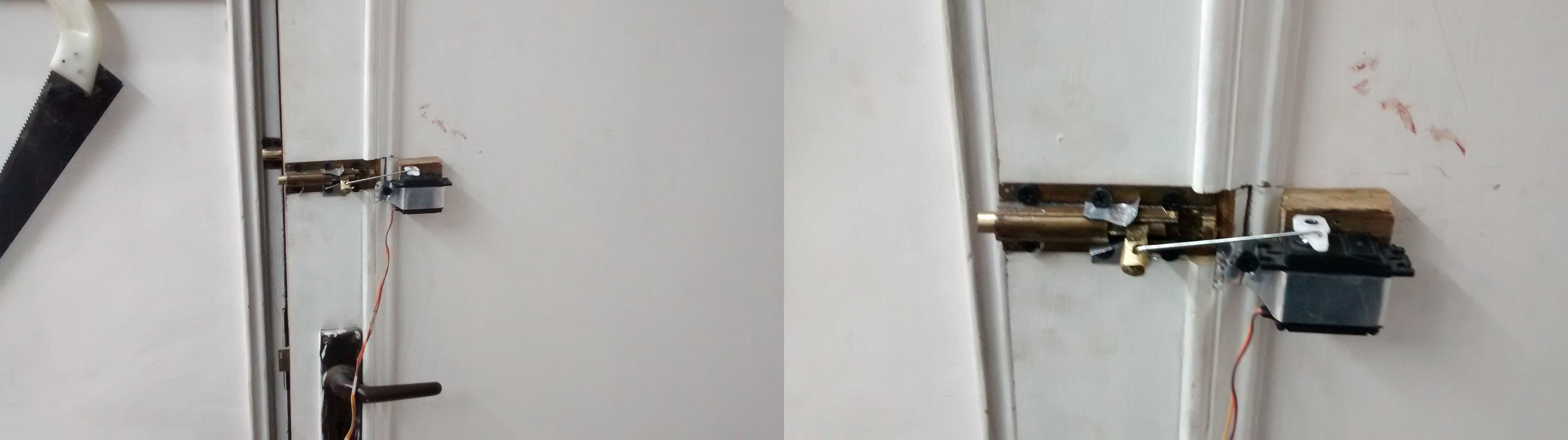
I attached the servo to the mechanical lock. Servo was tested independently to make sure it was locking and unlocking the door at 0 and 90 degrees or vice-versa.

Once I made sure that the locking hardware was functioning, I moved on to making an enclosure to house the micro-controller and all the extra electronics.
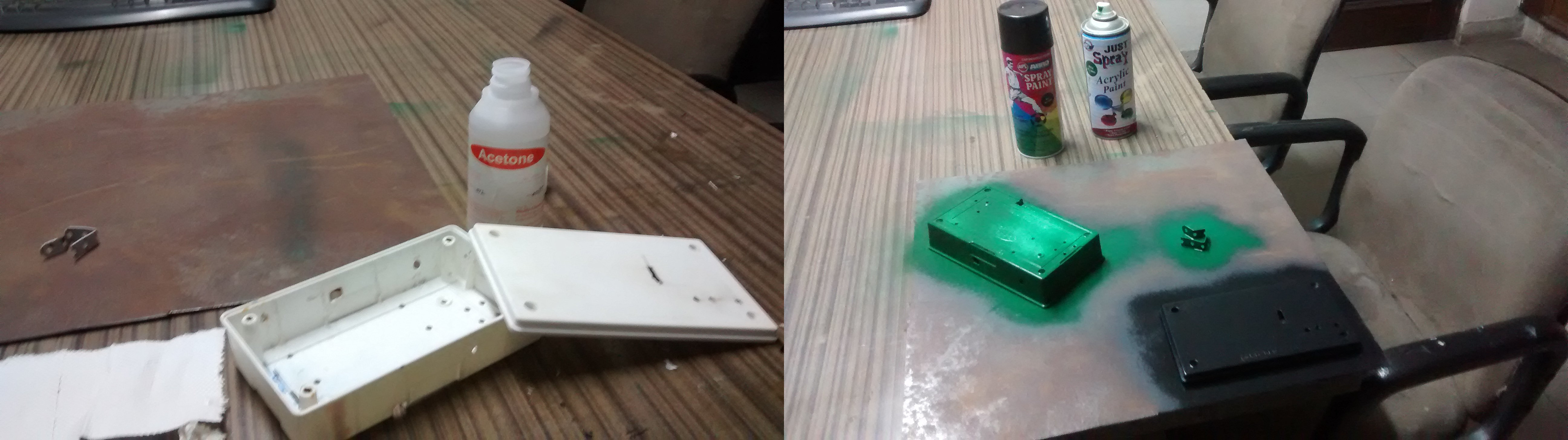
Once I finalized the enclosure, drilled all the required holes and made any slots to pass the cables, I cleaned the whole case with some acetone and spray painted it.
The front panel was matte black while the body was military green.
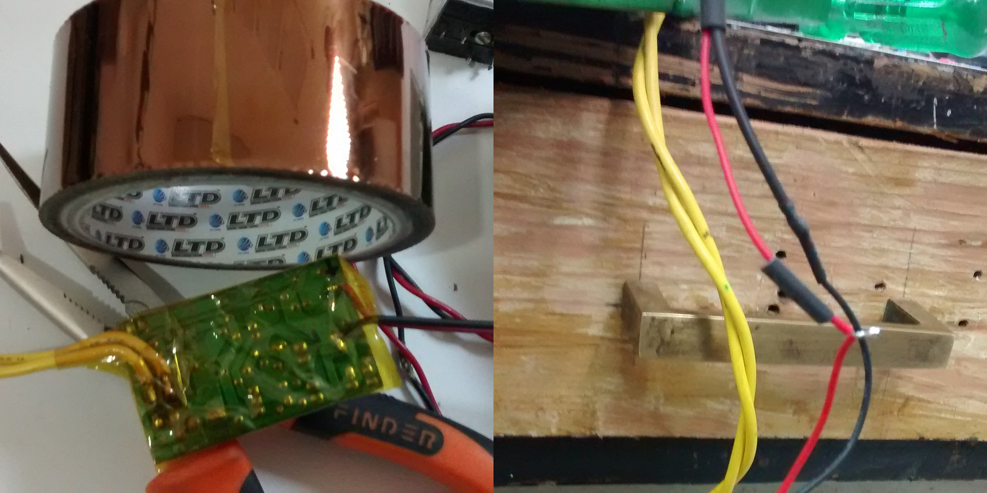
To power the electronics, I used a AC-DC adapter. The housing of the adapter was broken so I utilized only the circuit, making sure to solder wires properly and insulating all high-voltage connections with heat-resistant kapton tape.
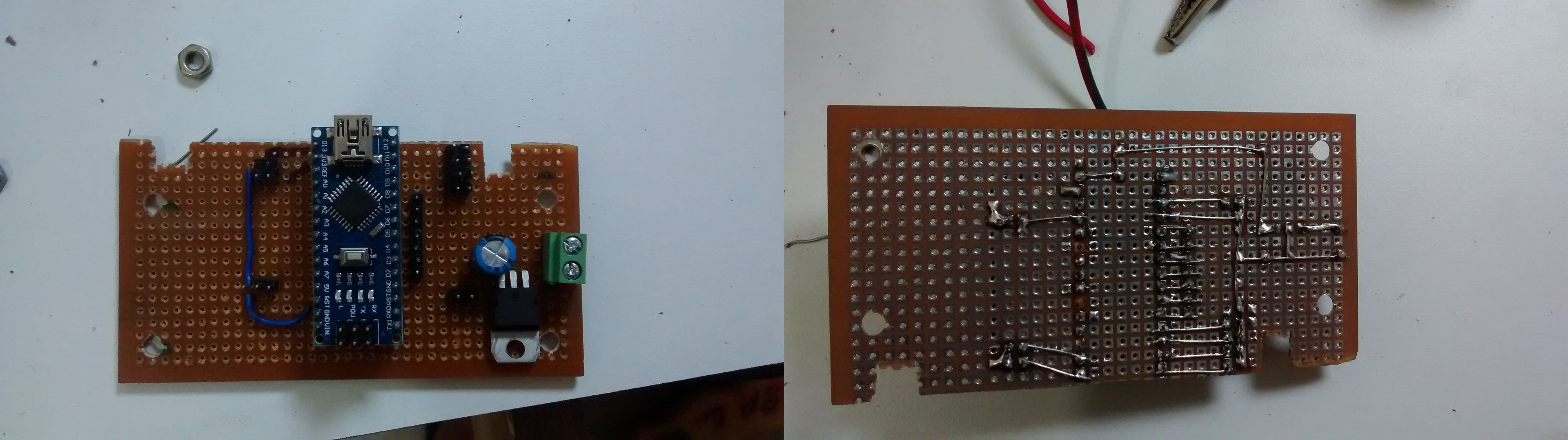
The 'brains' of the operation, an Arduino Nano micro-controller.
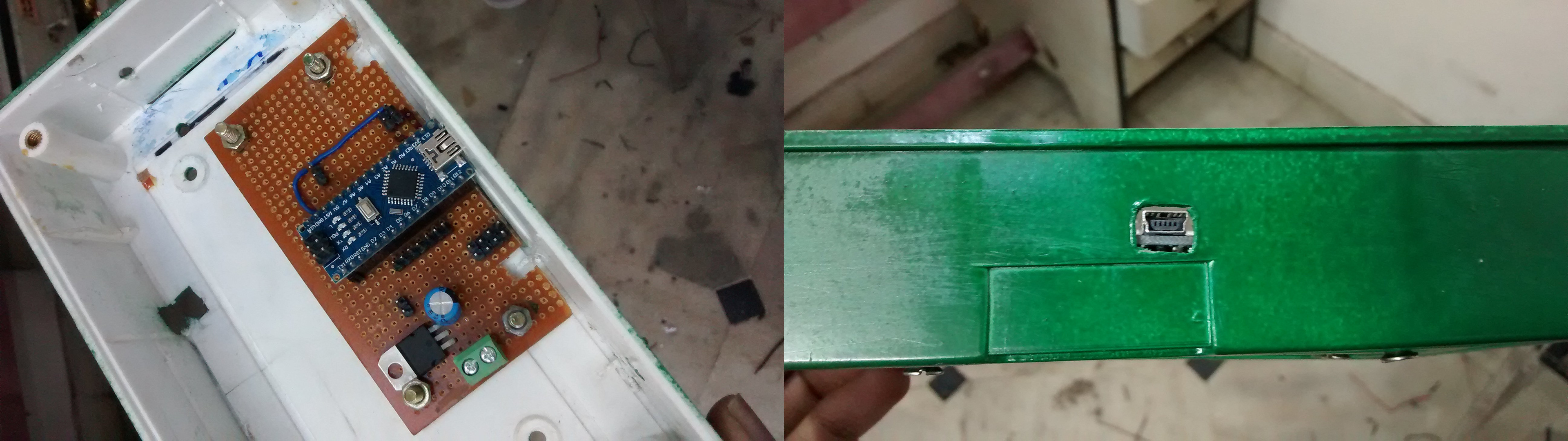
The Arduino was mounted inside the housing with a slot cut-out for the USB port in case I wanted to change the security code at a later time. This also serves as an 'external' power port to run the lock in case the power goes out.
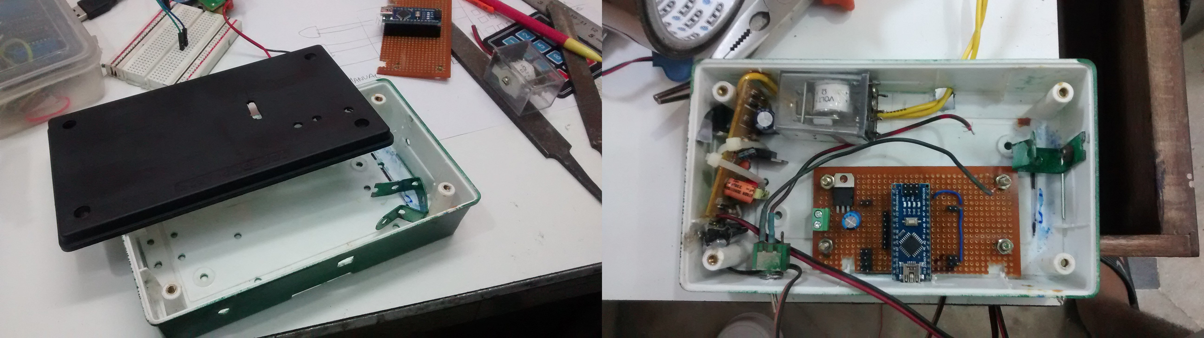
I added a relay that would switch the power source to a secondary 9V battery (pictured below) in case the power went out and I wanted to open the lock.
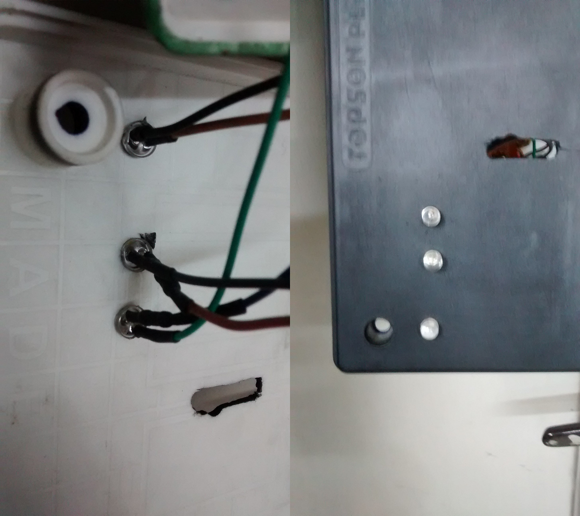
LED's in the front of the panel indicate the current lock status. Blue is for Power, Green is for Unlocked and Red is for Locked.
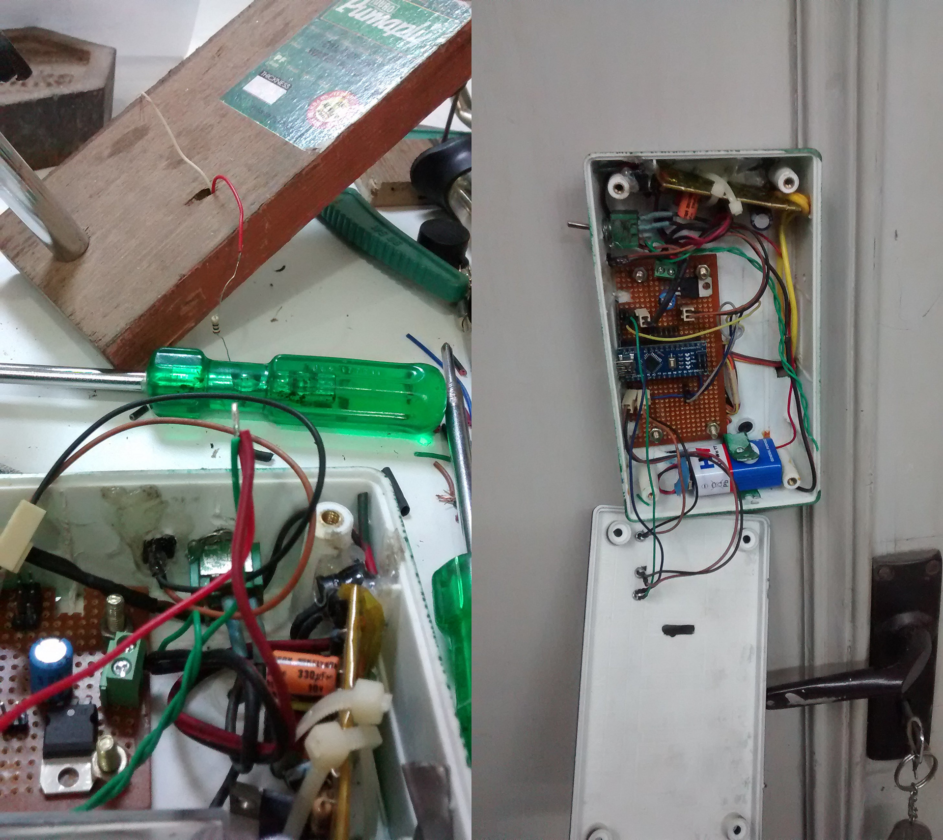
I added a switch to turn on the secondary power source when the power went out. This ensured that if and when the power went out and I was not using the space, the secondary battery would not get drained out. Also, there was a lot of wiring.